|
|||||||


| Register | Readers Rides | Gallery | FAQ | Members List | Social Groups | Calendar | Search | Today's Posts | Mark Forums Read |
 |
|
|
Thread Tools | Display Modes |
|
|
|
|||||||
| Register | Readers Rides | Gallery | FAQ | Members List | Social Groups | Calendar | Search | Today's Posts | Mark Forums Read |
|
|
|
Thread Tools | Display Modes |
 14-03-2015, 09:37 PM
|
#1 | ||
|
Junior Member
Join Date: Apr 2009
Location: Sydney
Car: Astina BG 1991 - Rx7 S4
Posts: 105
|
Exhaust Pipe Sizing
I got asked this, so I'll answer it here in-case anybody else wants to read it.
Quote:
Quote:
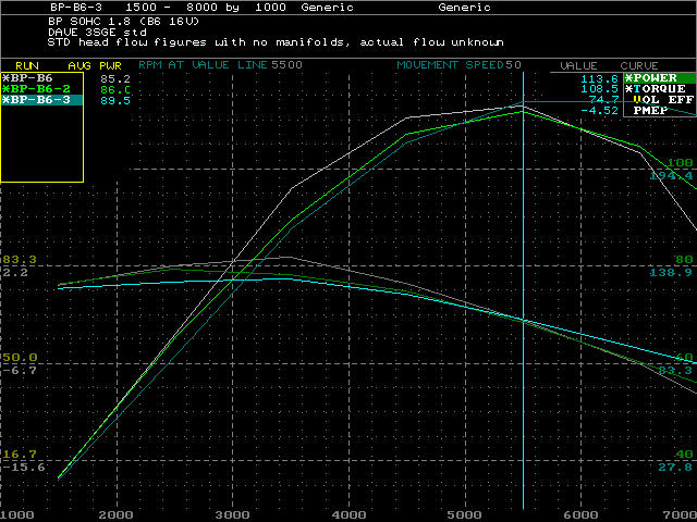
Imagine an engine that has a volumetric efficiency of 125% - high end race engine -. Now pull the head off and put a flat plate on it with only valves and no manifolds. That engine will now have trouble reaching a VE of over 100%, because it only has piston demand to fill it. Now subtract 100% from 125%, and you see that the manifolds are adding 25% more power to an engine. But the kicker is, manifolds can only add power at certain rpm points because the piping goes in and out of tune at different rpm due to wave tuning. Imagine a pressure sensor in the port just above the intake valve.  Look at the light blue line on the top graph at IVC(inlet valve close)(right side of graph). The valve is closing, and the energy of the air column slowing is raising the pressure at the sensor. The valve shuts and the wave now runs back out to the ram tube entry leaving the pressure low at the sensor. The wave reflects when it reaches atmosphere, and now returns making the pressure go up again near EVO(left side of the graph). This is the 1st harmonic. It is the biggest wave, but no one uses it because the manifold has to be ridiculously long. The wave bounces back and pressure is low again, and then it returns to make the pressure high again. The 2nd harmonic. The 2nd wave is used sometimes in production engines, if there is enough room for long manifolds. Again the pressure drops and rises making the 3rd harmonic. Notice the 3rd wave peeks at IVO, and the rise in pressure pushes air into the cyl even though the piston is still rising before TDC(dotted line between IVO EVC) The timing is adjusted by lengths of the piping, but the strength is adjusted by velocity. The faster a mass of air, the more force it can apply to ram air back into a cylinder due to returning waves. To see velocity in action open a water tap so it's flowing fast, and then shut it as fast as you can. The mass of the water stopping quickly makes the pipes rattle. The problem is that you can't make the velocity faster and faster, you need to balance the fastest velocity so that it doesn't loose too much flow. Flow is pretty well understood these day, so much so that you can look at something and use common scene to judge if it flows good or not. Basically make pipes straight with no steps in the wrong direction, and if you have to make a turn make it as gradual as will fit in the area. In an inlet there is a sweat spot of 0.6 mach, or 700ft/s, but that is dictated by what the port looks like. The older the port design the lower the sustainable intake port velocities it can handle :- 1960s port where the air has to turn 90º from port to valve exit has to be sized for 500-550ft/s intake air speeds. BP 16V DOHC where the turn is only 45º has to be sized for 650-700ft/s You can design a 1960"s V8 port to run at 700ft/s, and it might make the same HP, but it will produce less torque. I will add practical examples when I have time Last edited by Old Grey; 14-03-2015 at 09:58 PM. |
||

|

|
| Sponsored Links |
|
|
|
15-03-2015, 08:44 AM
|
#2 |
|
Junior Member
Join Date: Apr 2009
Location: Sydney
Car: Astina BG 1991 - Rx7 S4
Posts: 105
|
Lets look at the B8(BP) 16V SOHC 1.8 and see what different specs do.
Baseline std 112.536 Cubic Inches @ 6000 RPM with 92.00 % Volumetric Efficiency PerCent Peak HorsePower --- 111.4hp Peak Torque Lbs-Ft - 108.1ft/lb Header Design Specs --- for 112.536 CID from 4000 to 6500 RPM 1st Y-Segment Dia.= 1.413 Length= 14.8 to 16.1 inches long 2nd Y-Segment Dia.= 1.538 Length= 14.8 to 16.1 inches long Header Collector Specs (Conventional Straight Tube) Diameter= 2.170 to 2.420 Tuned Lengths= 18.2 best and 9.1 or 36.3 Total Exhaust System Tuned Lengths (Primary ends to TailPipe end) Best HP/TQ Tuned Collector Lengths= 18.2 , 36.3 , 72.7 , 145.3 inches long Now increase the VE so it makes more power 112.536 Cubic Inches @ 6000 RPM with 110.00 % Volumetric Efficiency PerCent Peak HorsePower --- 148.7hp Peak Torque Lbs-Ft - 144.3ft/lb Header Design Specs --- for 112.536 CID from 4000 to 6500 RPM 1st Y-Segment Dia.= 1.339 Length= 13.1 to 14.4 inches long 2nd Y-Segment Dia.= 1.464 Length= 13.1 to 14.4 inches long Header Collector Specs (Conventional Straight Tube) Diameter= 2.044 to 2.294 Tuned Lengths= 16.8 best and 8.4 or 33.6 Total Exhaust System Tuned Lengths (Primary ends to TailPipe end) Best HP/TQ Tuned Collector Lengths= 16.8 , 33.6 , 67.2 , 134.4 inches long Notice the pipe sizes getting smaller Looking a the Hurricane the pipes are 41mm(1.61"), 44(1.73")mm, 57mm(2.24"). The lengths aren't stated so I have to guess from the photo - 1st seg - 14", 2nd seg - 14" http://www.hurricaneperformancevicto...au/ford-4-cyl/ Lets go back to the 1st std engine figures and see at what rpm the Hurricane tunes at. I can't actually get the Hurricane figures to line up because it has miss-matched components, but using 7000rpm and a lowering VE to keep the HP realistic is the closest. 112.536 Cubic Inches @ 7000 RPM with 75.00 % Volumetric Efficiency PerCent Peak HorsePower --- 92.9hp (actual engine would have less than 80hp@7000rpm) Peak Torque Lbs-Ft - 77.3ft/lb Header Design Specs --- for 112.536 CID from 5000 to 7500 RPM 1st Y-Segment Dia.= 1.623 Length= 14.3 to 15.6 inches long 2nd Y-Segment Dia.= 1.748 Length= 14.3 to 15.6 inches long Header Collector Specs (Conventional Straight Tube) Diameter= 2.529 to 2.779 Tuned Lengths= 17.0 best and 8.5 or 34.1 Just looking at the pipes it looks like the lengths are close, it's just the diameters are too big. Last edited by Old Grey; 16-03-2015 at 03:52 PM. |
|
|
|
|
15-03-2015, 07:57 PM
|
#3 |
|
Junior Member
Join Date: Apr 2009
Location: Sydney
Car: Astina BG 1991 - Rx7 S4
Posts: 105
|
This is roughly what it would be like to drive with the 3 pipes
 Light green - std Blue - Hurricane Pink - smaller pipes |
|
|
|
|
16-03-2015, 07:46 AM
|
#4 |
|
Junior Member
Join Date: Apr 2009
Location: Sydney
Car: Astina BG 1991 - Rx7 S4
Posts: 105
|
Lets look at the B8(BP) 16V SOHC 1.8 and see what different specs do.
Baseline std 112.536 Cubic Inches @ 6000 RPM with 92.00 % Volumetric Efficiency PerCent Peak HorsePower --- 111.4hp Peak Torque Lbs-Ft - 108.1ft/lb Header Design Specs --- for 112.536 CID from 4000 to 6500 RPM 1st Y-Segment Dia.= 1.413 Length= 14.8 to 16.1 inches long 2nd Y-Segment Dia.= 1.538 Length= 14.8 to 16.1 inches long Header Collector Specs (Conventional Straight Tube) Diameter= 2.170 to 2.420 Tuned Lengths= 18.2 best and 9.1 or 36.3 Total Exhaust System Tuned Lengths (Primary ends to TailPipe end) Best HP/TQ Tuned Collector Lengths= 18.2 , 36.3 , 72.7 , 145.3 inches long Higher RPM - change engine components so that the HP now peeked at 8000rpm - 112.536 Cubic Inches @ 8000 RPM with 92.00 % Volumetric Efficiency PerCent Peak HorsePower --- 154.5hp Peak Torque Lbs-Ft - 112.4ft/lb Header Design Specs --- for 112.536 CID from 6000 to 8500 RPM 1st Y-Segment Dia.= 1.632 Length= 10.8 to 12.1 inches long 2nd Y-Segment Dia.= 1.757 Length= 10.8 to 12.1 inches long Header Collector Specs (Conventional Straight Tube) Diameter= 2.544 to 2.794 Tuned Lengths= 13.6 best and 6.8 or 27.3 Notice pipes get shorter and larger in diameter. Last edited by Old Grey; 16-03-2015 at 03:53 PM. |
|
|
|
|
16-03-2015, 08:06 AM
|
#5 |
|
Junior Member
Join Date: Apr 2009
Location: Sydney
Car: Astina BG 1991 - Rx7 S4
Posts: 105
|
A pratical example of pipe sizes
We had a 427 Mustang that ran 10.3sec at 133mph down the ¼ mile with 1 3/4" pipes - they were left over from the 351 that was in the car before -. I calculated that 1 7/8" would be better, but the owner was cheap and used a set of 2" pipe he had lying around. We dyno-ed it and it made 500hp at the rear wheels. At the track the car went 10.3sec at 135mph. The car with the 1 3/4" pipes could easily wheelspin it's slicks on a sticky competition prepared track. But with the 2" pipes there so little torque that the tyres stuck and bogged the engine down, so much so that we had to pump the tyres up so that the wheels could spin and get back up to 10.3sec. The mph went from 133 to 135mph, which indicates that there is more power. It was pretty much what you would expect with bigger pipes, less torque and more power. |
|
|
|
|
17-03-2015, 07:44 AM
|
#6 |
|
Junior Member
Join Date: Apr 2009
Location: Sydney
Car: Astina BG 1991 - Rx7 S4
Posts: 105
|
A quick simulation of a B8(BP) 1.8 SOHC - I'll use B8 because our B6 is an 8 valve carb engine -.
Posted figures are The 1.8 L (1,839 cc) B8 (sometimes "BP") SOHC 103 hp (77 kW), 111 lb-ft (U.S./Canadian market) 106 PS (78 kW) at 5,300 rpm, 151 N·m (111 lb·ft) at 4,000 rpm (European markets) Pipe simulated is simple 4 into 1 Single Primary Pipe Specs --- for 112.536 CID from 3300 to 5800 RPM Diameter= 1.186 to 1.311 Length= 32.9 to 35.5 inches long Diameter= 2.496 Tuned Lengths= 20.2" Changing pipe diameters 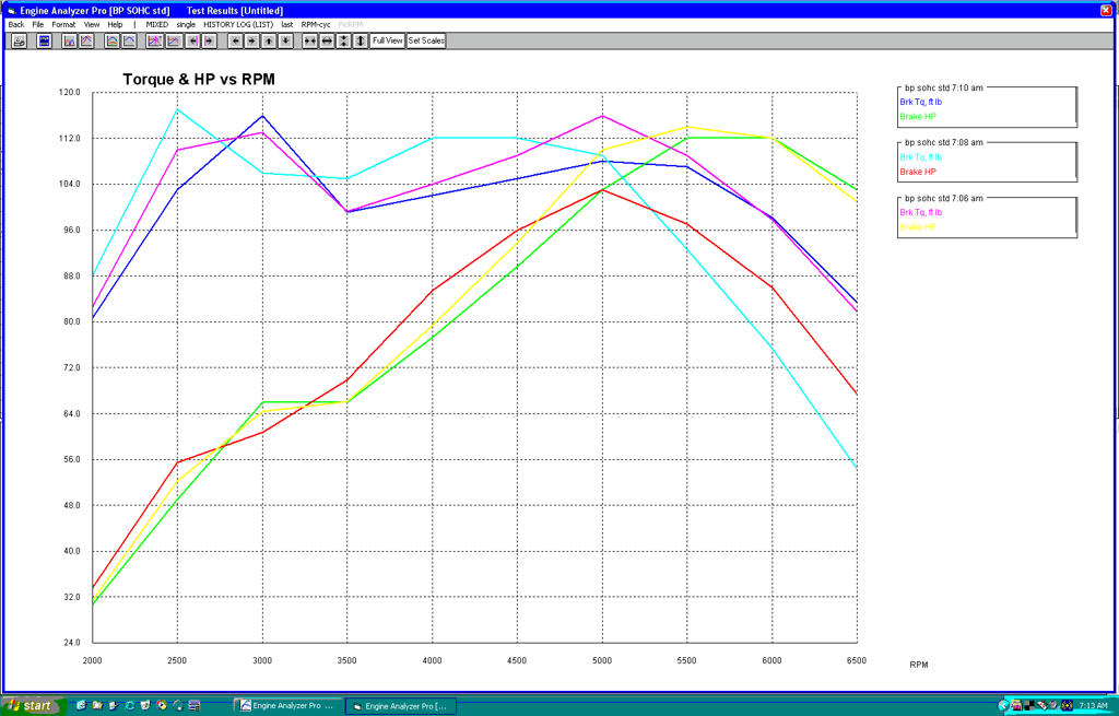 Changing Primary pipe diameters Yellow - 1.3" (pipe above) Red ---- 1.0" Green - 1.6" You can match torque curves from legend boxes on the right. Changing pipe lengths 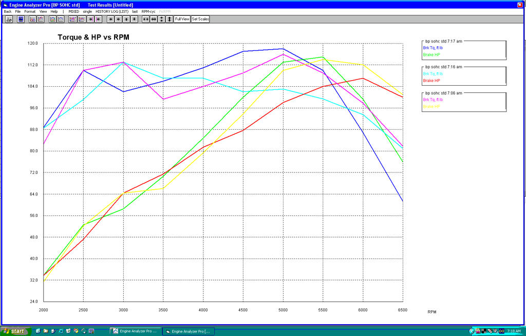 Changing Primary pipe lengths Yellow - 33" (pipe above) Red ---- 23" Green - 43" - has more torque by dies very quickly after peek HP These simulators aren't great, hence why I don't use them any more, but you'll get an idea of changes. Last edited by Old Grey; 17-03-2015 at 07:55 AM. |
|
|
|
|
20-03-2015, 10:36 AM
|
#7 |
|
Senior Member
 
Join Date: Sep 2004
Location: n/a
Car: n/a
Posts: 10,929
|
after peak is irrelevant.
you change at 5,500rpm, engine is at 4000rpm and the green one is still clapping along with better torque than the other 2 between 3.3K and 5.5K. |
|
|
|
|
| Thread Tools | |
| Display Modes | |
|
|


 Linear Mode

